Description
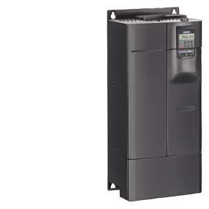
SIPLUS MM440 FS F 45 kW for medial exposure with conformal coating based on 6SE6440-2AD34-5FA1
| Product | ||||||||||||||||||||||||||||||||||||||||
| Article Number (Market Facing Number) | 6AG1440-2AD34-5FA1 | |||||||||||||||||||||||||||||||||||||||
| Product Description | SIPLUS MM440 FS F 45 kW for medial exposure with conformal coating based on 6SE6440-2AD34-5FA1 | |||||||||||||||||||||||||||||||||||||||
| Product family | Ordering Data Overview | |||||||||||||||||||||||||||||||||||||||
| Product Lifecycle (PLM) | PM400:Phase Out Started | |||||||||||||||||||||||||||||||||||||||
| PLM Effective Date | Product phase-out since: 01.10.2018 | |||||||||||||||||||||||||||||||||||||||
| Price data | ||||||||||||||||||||||||||||||||||||||||
| Price Group | ||||||||||||||||||||||||||||||||||||||||
| List Price | Show prices | |||||||||||||||||||||||||||||||||||||||
| Customer Price | Show prices | |||||||||||||||||||||||||||||||||||||||
| Surcharge for Raw Materials | None | |||||||||||||||||||||||||||||||||||||||
| Metal Factor | None | |||||||||||||||||||||||||||||||||||||||
| Delivery information | ||||||||||||||||||||||||||||||||||||||||
| Export Control Regulations | AL : N / ECCN : EAR99H | |||||||||||||||||||||||||||||||||||||||
| Standard lead time ex-works | 22 Day/Days | |||||||||||||||||||||||||||||||||||||||
| Net Weight (kg) | 0,001 Kg | |||||||||||||||||||||||||||||||||||||||
| Product Dimensions (W x L x H) | Not available | |||||||||||||||||||||||||||||||||||||||
| Packaging Dimension | 400,00 x 1200,00 x 620,00 | |||||||||||||||||||||||||||||||||||||||
| Package size unit of measure | MM | |||||||||||||||||||||||||||||||||||||||
| Quantity Unit | 1 Piece | |||||||||||||||||||||||||||||||||||||||
| Packaging Quantity | 1 | |||||||||||||||||||||||||||||||||||||||
| Additional Product Information | ||||||||||||||||||||||||||||||||||||||||
| EAN | 4025515140795 | |||||||||||||||||||||||||||||||||||||||
| UPC | Not available | |||||||||||||||||||||||||||||||||||||||
| Commodity Code | 85044088 | |||||||||||||||||||||||||||||||||||||||
| LKZ_FDB/ CatalogID | A&DSE/SIP ADD | |||||||||||||||||||||||||||||||||||||||
| Product Group | 4576 | |||||||||||||||||||||||||||||||||||||||
| Country of origin | Germany | |||||||||||||||||||||||||||||||||||||||
| Compliance with the substance restrictions according to RoHS directive | Since: 01.01.2012 | |||||||||||||||||||||||||||||||||||||||
| Product class | C: products manufactured / produced to order, which cannot be reused or re-utilised or be returned against credit. | |||||||||||||||||||||||||||||||||||||||
| WEEE (2012/19/EU) Take-Back Obligation | Yes | |||||||||||||||||||||||||||||||||||||||
| Classifications | ||||||||||||||||||||||||||||||||||||||||
|
||||||||||||||||||||||||||||||||||||||||
Technical specifications
| Technical data | MICROMASTER 440 | ||||||||
|---|---|---|---|---|---|---|---|---|---|
| Mains voltage and power ranges | CT (constant torque) | VT (variable torque) | |||||||
| 200 V to 240 V 1 AC ±10 % | 0.12 kW to 3 kW | – | |||||||
| 200 V to 240 V 3 AC ±10 % | 0.12 kW to 45 kW | 5.5 kW to 55 kW | |||||||
| 380 V to 480 V 3 AC ±10 % | 0.37 kW to 200 kW | 7.5 kW to 250 kW | |||||||
| 500 V to 600 V 3 AC ±10 % | 0.75 kW to 75 kW | 1.5 kW to 90 kW | |||||||
| Input frequency | 47 Hz to 63 Hz | ||||||||
| Output frequency | in V/f mode
|
for inverter 0.12 kW to 75 kW | 0 … 650 Hz, (limitation to 550 Hz in production to comply with legal requirements) 1) | ||||||
| for inverter 90 kW to 200 kW | 0 Hz to 267 Hz | ||||||||
| in vector mode
|
for inverter 0.12 kW to 75 kW | 0 Hz to 200 Hz | |||||||
| for inverter 90 kW to 200 kW | 0 Hz to 200 Hz | ||||||||
| Power factor | ≥ 0.95 | ||||||||
| Inverter efficiency | 0.12 kW to 75 kW: 96 % to 97 %; 90 kW to 200 kW: 97 % to 98 % | ||||||||
| Overload capability
CT mode |
for inverter 0.12 kW to 75 kW | Overload current 1.5 x rated output current (i.e. 150 % overload capability) for 60 s, cycle time 300 s, and 2 x rated output current (i.e. 200 % overload capability) for 3 s, cycle time 300 s | |||||||
| for inverter 90 kW to 200 kW | Overload current 1.36 x rated output current (i.e. 136 % overload capability) for 57 s, cycle time 300 s, and 1.6 x rated output current (i.e. 160 % overload capability) for 3 s, cycle time 300 s | ||||||||
| Overload capability
VT mode |
for inverter 5.5 kW to 90 kW | Overload current 1.4 x rated output current (i.e. 140 % overload capability) for 3 s, and 1.1 x rated output current (i.e. 110 % overload capability) for 60 s, cycle time 300 s | |||||||
| for inverter 110 kW to 250 kW | Overload current 1.5 x rated output current (i.e. 150 % overload capability) for 1 s, and 1.1 x rated output current (i.e. 110 % overload capability) for 59 s, cycle time 300 s | ||||||||
| Inrush current | not higher than rated input current | ||||||||
| Control method | Vector control, torque control, linear V/f characteristic; quadratic V/f characteristic; multipoint characteristic (programmable V/f characteristic); flux current control (FCC) | ||||||||
| Pulse frequency | for inverter 0.12 kW to 75 kW | 4 kHz (standard); 16 kHz (standard with 230 V inverters 0.12 kW to 5.5 kW) 2 kHz to 16 kHz (in 2 kHz steps) |
|||||||
| for inverter 90 kW to 200 kW | 2 kHz (standard with VT mode); 4 kHz (standard with CT mode) 2 kHz to 4 kHz (in 2 kHz steps) |
||||||||
| Fixed frequencies | 15, programmable | ||||||||
| Skip frequency ranges | 4, programmable | ||||||||
| Setpoint resolution | 0.01 Hz digital 0.01 Hz serial 10 bit analog |
||||||||
| Digital inputs | 6 fully programmable isolated digital inputs; switchable PNP/NPN | ||||||||
| Analog inputs | 2 programmable analog inputs
|
||||||||
| Relay outputs | 3, programmable 30 V DC/5 A (resistive load) 250 V AC/2A (inductive load) |
||||||||
| Analog outputs | 2, programmable (0/4 mA to 20 mA) | ||||||||
| Serial interfaces | RS-485, optional RS-232 | ||||||||
| Motor cable lengths | Without output choke | for inverter 0.12 kW to 75 kW | max. 50 m (shielded) max. 100 m (unshielded) |
||||||
| for inverter 90 kW to 250 kW | max. 200 m (shielded) max. 300 m (unshielded) |
||||||||
| With output choke | see variant dependent options | ||||||||
| Electromagnetic compatibility (see Selection and Ordering Data) | EMC filter, Class A or Class B to EN 55 011 available as an option Inverter with internal filter Class A available |
||||||||
| Braking | Resistance braking with DC braking, compound braking, integrated brake chopper (integrated brake chopper only with 0.12 kW to 75 kW inverters) | ||||||||
| Degree of protection | IP20 | ||||||||
| Operating temperature (without derating) | for inverter 0.12 kW to 75 kW | CT: -10 °C to +50 °C (+14 °F to +122 °F) VT: -10 °C to +40 °C (+14 °F to +104 °F) |
|||||||
| for inverter 90 kW to 200 kW | 0 °C to +40 °C (+32 °F to +104 °F) | ||||||||
| Storage temperature | -40 °C to +70 °C (-40 °F to +158 °F) | ||||||||
| Relative humidity | 95 % (non-condensing) | ||||||||
| Installation altitude | for inverter 0.12 kW to 75 kW | up to 1000 m above sea level without derating | |||||||
| for inverter 90 kW to 200 kW | up to 2000 m above sea level without derating | ||||||||
| Standard SCCR (Short Circuit Current Rating) 2) |
FSA, FSB, FSC: 100 kA FSD, FSE, FSF, FSFX, FSGX: 65 kA |
||||||||
| Protection features for | Undervoltage, overvoltage, overload, earth faults, short-circuits, stall prevention, locked motor protection, motor overtemperature, inverter overtemperature, parameter change protection | ||||||||
| Compliance with standards | uL, c uL, CE, c-tick | ||||||||
| CE marking | Conformity with low-voltage directive 73/23/EEC | ||||||||
| Cooling-air volumetric flow required, dimensions and weights (without options) | Frame size (FS) | Cooling-air volumetric flow required (l/s)/(CFM) | H x W x D, max. (mm) | Weight, approx. (kg) | |||||
| A | 4.8/10.2 | 173 x 73 x 149 | 1.3 | ||||||
| B | 24/51 | 202 x 149 x 172 | 3.4 | ||||||
| C | 54.9/116.3 | 245 x 185 x 195 | 5.7 | ||||||
| D | 2 x 54.9/2 x 116.3 | 520 x 275 x 245 | 17 | ||||||
| E | 2 x 54.9/2 x 116.3 | 650 x 275 x 245 | 22 | ||||||
| F without filter | 150/317.79 | 850 x 350 x 320 | 56 | ||||||
| F with filter | 150/317.79 | 1150 x 350 x 320 | 75 | ||||||
| FX | 225/478.13 | 1400 x 326 x 356 | 116 | ||||||
| GX | 440/935 | 1533 x 326 x 545 | 174 | ||||||
| CFM: Cubic Feet per Minute |
|
||||||||


