Description
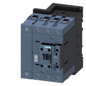
Order No.: 3RT23441AP60 3RT2344-1AP60 Contactor, 4 NO, AC-1: 110 A 220 V AC/50 Hz/240 V AC/60 Hz 4-pole, 4 NO, Size S3 Screw terminal 1 NO+1 NC integrated
Overview
Contactors AC-1, up to 525 A, 4-pole bottom row: 3RT230 to 3RT234 contactors (sizes S00 to S3) top row: 3RT135 to 3RT137 contactors (sizes S6 to S12)
Standards
IEC/EN 60947‑1, IEC/EN 60947‑4‑1, IEC/EN 60947‑5‑1 (auxiliary switches)
Sizes S00 to S3
The 3RT23 contactors have two auxiliary contacts with 1 NO and 1 NC.
Sizes S6 to S12
The 3RT13 contactors have two auxiliary contacts with 2 NO and 2 NC.
Connection methods
Main circuit
-
- Sizes S00 and S0: screw or spring-type terminals, spring-type terminals with convenient plug-in design for device connectors
- Sizes S2 and S3: screw terminals with box terminal; direct connection to the connecting bar possible with cable lugs for S3 when the box terminal is removed.
- Sizes S6 to S12: screw terminals with connecting bars that the cables can be connected to using either cable lugs or flexible or rigid busbars. Sizes S10 and S12 can be fitted with offset bus connectors.
Auxiliary/control circuit
-
- Sizes S00 to S3: screw or spring-type terminals
- Sizes S6 to S12: Screw terminals
Operating mechanism types
Sizes S00 to S3
3RT23 contactors are available as versions with conventional AC or DC operating mechanisms or as versions with a wide-range solid-state operating mechanism and a universal actuating voltage (AC or DC operation possible).
With an operating range between 0.8 to 1.1 x Us, control takes place via the control supply voltage connection A1 – A2 as is typically the case.
Sizes S6 to S12
The 3RT13 contactors are fitted with a wide-range solid-state operating mechanism that can be controlled with both 50/60 Hz AC and DC.
The operating range of the DC control is 0.8 x Us min and 1.1 x Us max, and for AC operation 0.85 x Us min and 1.1 x Us max.
It is not possible to change the operating mechanism.
Mounting of additional auxiliary contacts
Size S00
Four auxiliary contacts, including no more than three NC contacts
Sizes S0 to S3
Four additional auxiliary contacts, including no more than two NC contacts
Sizes S6 to S12
One additional auxiliary switch with 1 NO + 1 NC can be mounted on each side.
Accessories and spare parts
-
- Sizes S00 to S3: see Accessories and Spare Parts
- Sizes S6 to S12: See following accessories in the overview graphic or accessories ordering data
3RT135 to 3RT137 contactors, sizes S6 to S12 with mountable accessories
Application
The contactors are suitable:
-
- For switching resistive loads
- For disconnecting from power systems (with neutral conductor to be switched)
- For system transfers when alternative AC power supplies are used
- Use as contactors which only carry current and do not have to switch in case of inductive loads – e.g. variable-speed drives
- For switching mixed loads in distribution systems (e.g. for supplying heaters, lamps, motors, PC power supply units) with p.f. > 0.8 according to IEC 60947‑4‑1, test conditions for utilization category AC‑1.
For a general description of sizes S00 to S3 of 3RT23 contactors, see SIRIUS 3RT contactors, 3-pole up to 250 kW.


