Description
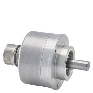
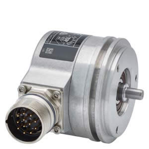
6FX2001-4SA10 6FX20014SA10 INCREM. ENCODER 6FX2001-4SA10 WITH HTL, 100 P/R, OPERATING VOLTAGE 10-30V CLAMP FLANGE SHAFT 10 MM AXIAL FLANGE CONNECTOR6FX2001-4SA10_datasheet_en
Function of Incremental encoders
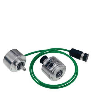
Incremental encoder with sin/cos 1 Vpp and nd clamp flange incl. cable with connector as well as incremental encoder with RS422/HTL and Synchro flange
Incremental encoders detect relative movement and deliver a defined number of electrical pulses per revolution, which represent the measurement of the traveled distance or angle.
Incremental encoders operate on the principle of optoelectronic scanning of dividing discs with the transmitted light principle. The light source is a light emitting diode (LED). The light-dark modulation generated as the encoder shaft rotates is picked up by photoelectronic elements. With an appropriate arrangement of the line pattern on the dividing disk connected to the shaft and the fixed aperture, the photoelectronic elements provide two trace signals A and B at 90° to one another, as well as a reference signal R. The encoder electronics amplify these signals and convert them to different output levels.
Signal levels
The following signal levels are available for the incremental encoders:
| Signal level | Benefits |
| Analog signals sin/cos with level 1 Vpp | The analog signal allows the digitization of the trace signals. In order to obtain a fine resolution, the signals are interpolated in the higher-level controller. |
| RS422 differential signals (TTL) | The resolution can be quadrupled by means of edge evaluation. |
| HTL (High Voltage Transistor Logic) | Built-on encoders with an HTL interface are designed for applications with digital inputs with a 24 V level. The resolution can be quadrupled by means of edge evaluation.
|

